Introduction
Bluetooth Low Energy performance starts at the Physical Layer (PHY), not in your GATT design or connection settings. You can build a clean architecture and optimize every parameter, but if the RF is weak, noisy, or unstable, the product will fail where it matters most.
In real-world environments, poor RF shows up as dropped connections, reduced range, and inconsistent behavior. RF quality is what ultimately determines whether your device feels reliable or frustrating to use.
This guide walks through RF PHY testing for BLE from an engineering perspective. We cover what matters, how to measure it, and how to interpret results. Our experience developing and testing countless devices shows that doing this early in the process helps avoid expensive hardware re-spins and bugs that affect development.
Having a clear and consistent process lets you deliver a great product with reliable connections and long range.

What PHY Testing Actually Means in BLE
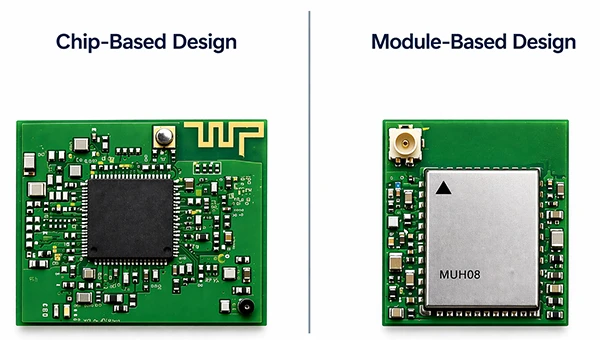
When you’re designing a Bluetooth LE or Classic product, you’ll integrate a BLE or Dual Mode radio in your design. This usually means one of two things:
- A Chip-based design
- A Module based Design
With a Module based design, you have a ready-to-go design you can integrate. Aside from the antenna, the RF performance of the module is mostly set and usually will be pretty good provided you follow the module vendor’s instructions.
The module’s Antenna performance is really the only thing left. We won’t cover Antenna issues in this guide as it’s a huge topic on it’s own, and in fact the Radio’s RF performance only makes any antenna issues worse.
While you can and should perform the testing we’ll talk about designs with BLE module, especially if the vendor is unknown, for the most part the reason you’re using a module is to save on RF design and certification costs.
The module is a known quantity and will have an FCC ID with Modular approval you can leverage in your own design. The integration job will mostly determine the performance of the antenna.
It’s still possible to impact the RF design of the module with noise or wrong design choices, so the PHY tests are still useful. We tend to perform a smaller number of tests to validate the overall design with Modules.
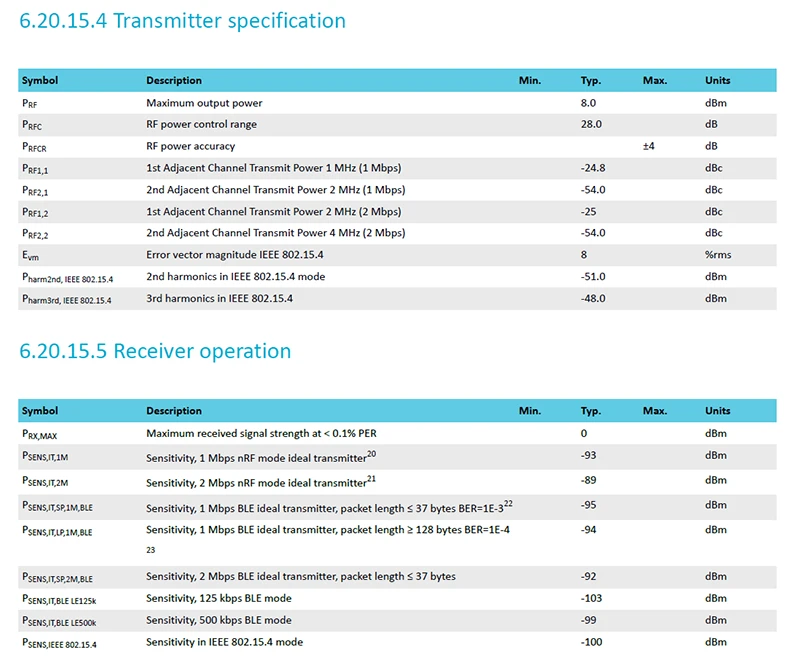
In a Chip-based design you’re using a chip directly from the manufacturer like Nordic Semiconductor, Silicon Labs or others. Your starting reference point for PHY performance is the datasheet for that part, as that will be essentially the best you can get.
Chipset manufacturers test their chips and try to squeeze as much performance as possible from the part. But it’s important to make sure that the way they got that data is realistic. It’s possible for vendors to cut corners in ways that make their devices look strong on paper but fall short in real-world use.
Your job as the product designer is to get as close as possible to that performance within the envelope of your design. Sometimes it’s straightforward, but more often it gets complicated.
Below you can see the Radio TX and RX specification for the Nordic Semiconductor nRF52840 radio. Things like maximum output power and sensitivity are critical parameters that you should be aware of, as well as the conditions under which these were measured.
One additional reason to perform PHY measurements is to test a part in conditions that the manufacturer either hasn’t tested or doesn’t provide data for. High or Low Temperatures is one such case.
The job of the RF PHY Testing is to give you an exact understanding of where your design stacks up against the reference design and other devices. After all, you can’t improve what you haven’t measured, and releasing a wireless product blindly is a recipe for disaster.
You may have also heard of Bluetooth SIG PHY Testing. If you’re using a module, you can rely on that module’s PHY Testing report (another benefit of using a module). But, if you’re doing your own design, you will need to work with the lab to test your design and pass. This isn’t necessarily difficult – vendors like Silicon Labs and Nordic go to a lot of effort to design a radio chip that will pass these tests. But you can still fail with a bad design.
You don’t want to send a radio design to the lab and be surprised that it fails. You’ll need to pay for re-tests and it can add weeks of delay. You want to know you will pass well ahead of time. But there’s a secret most designers don’t know:
The labs don’t actually test that your radio works well!
That’s right. You can create a design that passes all Bluetooth SIG and FCC tests and performs terribly in the real world- bad range, connection drops, etc. The FCC and the Bluetooth SIG aren’t there to help ensure your design works. They only care that it meets certain specifications like not radiating harmonics, occupying a limited bandwidth or exceeding field strength limitations.
So our goal with RF PHY Testing is to both make sure that we can pass the Bluetooth SIG tests and make sure our radio works to the limits of its capabilities, not just passes certifications
As an example, we had a customer years ago that had another product design build a Bluetooth Classic device using a 2 layer board. That saved on costs but caused a completely non-existent ground plane. This radiated RF at various harmonics. Because the product was at an advanced stage (almost production), redesigning it wasn’t an option. So what was the solution? We were forced to reduce the output power to get the harmonics under control. This caused the range of the product to drop.
Did the product pass FCC and BT SIG testing? Yes. Did it perform at its best? No. And Early testing would have helped
At the BLE PHY layer, you’re dealing with:
- Modulation: GFSK (Gaussian Frequency Shift Keying)
- Frequencies: 2.4 GHz ISM band (2402–2480 MHz)
- Sensitivity: Typically -94dBm to -100dBm
- TX Output Power: Typically -20dBm to +4dBm
- Data rates:
- 1M PHY (standard)
- 2M PHY (high throughput)
- LE Coded PHY (S=2, S=8 for long range)
PHY testing validates whether your device is:
- Transmitting clean, compliant RF signals
- Receiving signals reliably under real conditions
- Operating within Bluetooth SIG specifications
It’s important to remember that Bluetooth PHY testing performed by the labs doesn’t look to ensure that your radio performs at its best, but the metrics you can get will guide you towards that.
Key RF PHY Metrics You Need to Measure
Now that we understand in general why we need to do the PHY testing, let’s take a look at some of the critical parameters that need to be measured
Output Power
The output power is the actual RF power your device transmits and it’s a number given in dBm or less commonly in milliwatts.
The higher the RF power, the longer the range your signal can be received. But there are limits both as far as chip capabilities and limitations imposed by the FCC (and the Bluetooth SIG as well). Higher output power also consumes more power and reduces efficiency.
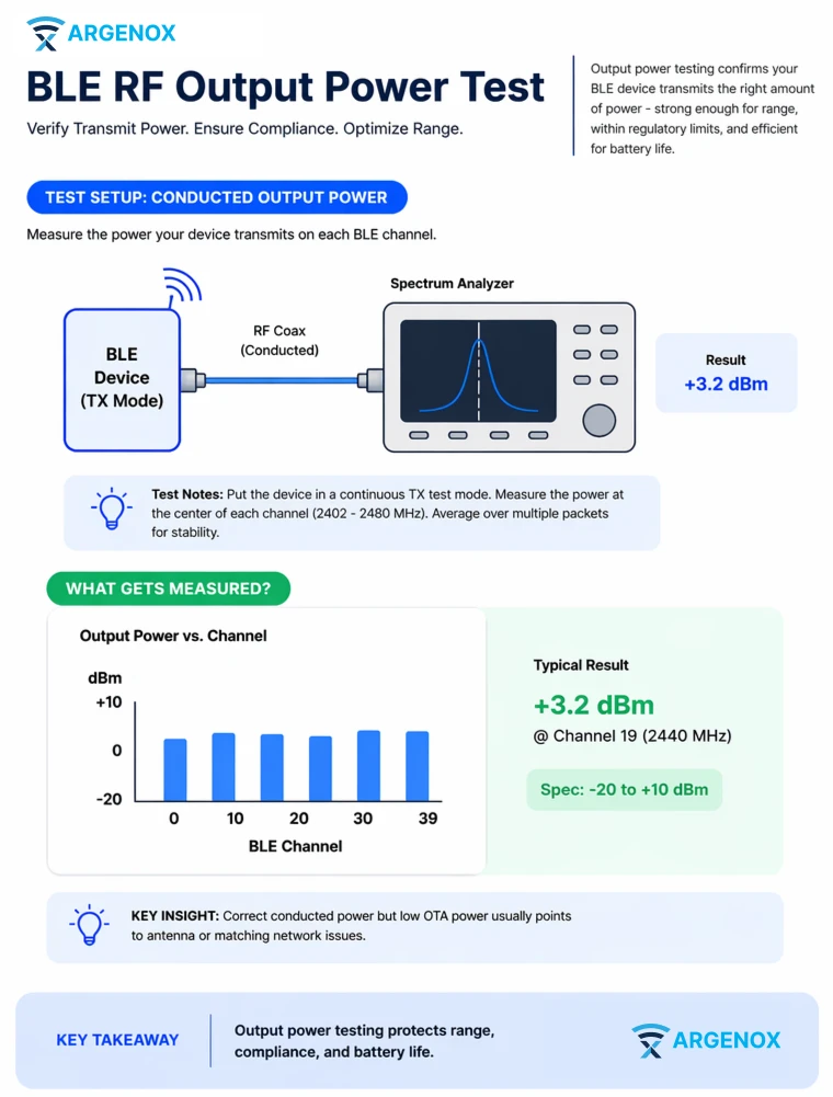
Most Bluetooth output power will be between 0dBm and 20dBm. The maximum output power depends mainly on your radio, or, if you have a Front End module (FEM), on that FEM.
If you’re configuring the BLE radio to 10dBm but are only getting 5dBm as measured at the output, it means your RF design or antenna are not working well. If your output power is low your range will be poor, and if it’s too high you’ll fail the FCC limits.
The higher the output power, the higher the power consumption. The vast majority of BLE and Bluetooth designs are battery powered, and you want a good and efficient design that will transfer all the power to the antenna with minimal losses. This could allow you to reduce the output power overall because you’re not having to compensate for losses.
RF Output Power target
Typical RF losses tend to be around 0.5dB to 2dB. A good RF design with good components, layout and RF matching will minimize this. Long traces or inefficient cables can reduce this, as can adding bandpass filters to protect against other transmitters. Every
Test method
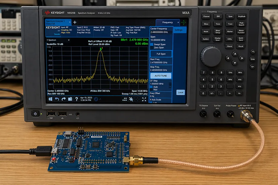
Testing the output power is done primarily via Conducted measurements by connecting a cable to the RF output of the device and compensating for any test cable losses. The device is placed in a Continuous Wave (CW) mode that generates a sinewave at the proper frequency with the right.
The output is measured using a spectrum analyzer or BLE tester at various frequencies and ideally under different temperature conditions and different channels.
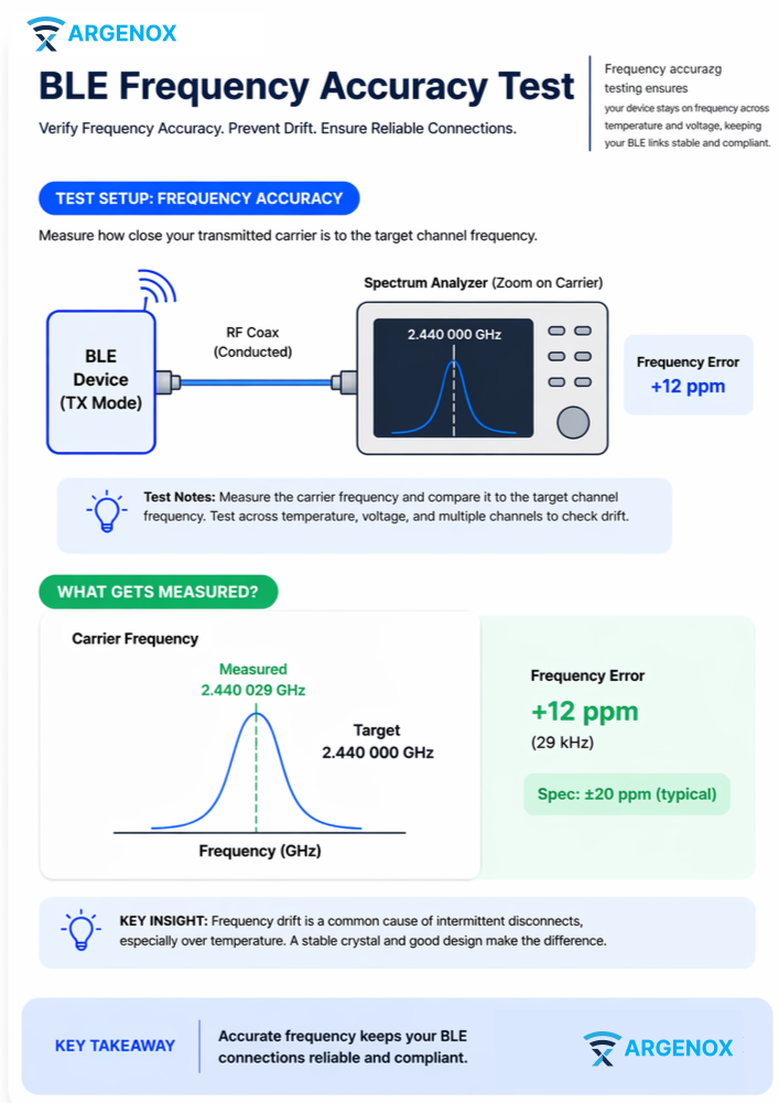
Frequency Accuracy & Drift
What it is
Bluetooth Radios generate radio frequencies, and how accurately they do this depends on a variety of factors such as the crystal used as the frequency reference.
Bluetooth testing measures how much the carrier frequency drifts from the intended channel frequency, and the Bluetooth Special Interest Group sets specific limits on how much deviation is allowed.
Why Test
- BLE receivers have strict frequency tolerance limits, and exceeding them will lead to failure in Bluetooth Special Interest Group PHY compliance testing.
- Carrier frequency can drift due to multiple effects that add on top of crystal offset such as temperature, aging, causing packet loss and connection issues
Key specs
- Typically ±20 ppm (depends on crystal and design)
Test considerations
Measure at least 3 units across:
- Temperature range
- Supply voltage variation
- Time (warm-up drift)
Improving Performance
You will need to compensate for the offset by adjusting the loading capacitors, which are usually external but can be internal to the device. it’s important to measure multiple units to ensure that the capacitors represent the typical unit.
Receiver Sensitivity
Receiver sensitivity is one of the most important parameters in a Bluetooth radio. It determines the weakest signal your device can receive and still decode the packets. The lower (more negative) this number, the better because it means your radio can decode weaker signals.

As a reference, modern designs get close to -100dBm, although most Bluetooth LE radios are capable of -96dBm to -98dBm.
This number is the best the radio can do. In practice, the RF losses will cause the actual design sensitivity to be worse. How bad depends on the design. Some designs lose over 2dB of sensitivity or more.
To give you a perspective, a 3dB loss in sensitivity means about 30% less range (all else being equal). A 6dB loss means 50% less range.
Because these effects are cumulative, it can be hard to get ideal sensitivity. For example, a bandpass filter to guard against high power cellular transmitters can add 1dB of loss (or more), and a trace in between can add another dB, which doesn’t account for component losses, tolerances, etc.
It’s important to know that the Receiver sensitivity performance is closely related to the TX Output Power performance. Passive RF circuits will have the same losses for TX and RX (if it’s the same route used for both). So, if the power output has dropped by 2dB, you can be sure that the sensitivity is impacted as well.
Why BLE Receiver Sensitivity Matters
- Sensitivity directly determines range
- Better sensitivity means less output power and less power consumption
Measuring Sensitivity
The sensitivity level is defined as the lowest signal level at which you achieve a certain Packet error rate. The device under test is configured using the Device Test Mode (DTM) to send BLE packets and the receiver measures how many of them are in error – they fail to be fully decoded (the data is predictable). While sending packets, the attenuation between the devices is increased until the error rate reaches the error rate is reached. That’s the sensitivity limit.
The Bluetooth SIG specifies the Packet Error Rate (PER) which needs to be ≤ 30% at the following levels
| PHY Mode | Minimum Sensitivity |
|---|---|
| LE 1M PHY | −70 dBm |
| LE 2M PHY | −70 dBm |
| LE Coded PHY (S=8, 125 kbps) | −82 dBm |
| LE Coded PHY (S=2, 500 kbps) | −75 dBm |
These values are the minimum compliance threshold. Terrible designs have passed these specifications with flying colors. The Bluetooth specifications’ job is to ensure minimum interoperability, not optimal performance of radios.
Vendor Bit Error Rate
Most BLE chipset vendors however don’t use the Packet Error Rate (PER) and instead use Bit Error Rate (BER). This parameter measures the radio performance itself and helps you compare apples to apples between radios since it depends only on the radio and the design and not the protocol mode.
Measuring BER is not straightforward because BLE uses CRC at the packet level and drops corrupted packets – you can’t really tell which individual bits were good or bad. So you won’t see this with regular radios.
To properly measure BER one needs to use a BLE Tester such as a Rhode and Schwarz CBT or CMW or from most other large test equipment vendors which are capable of measuring both PER and BER. As an alternative you can estimate the BER from the PER by using the PRBS9 payload, and counting error rates. For small bit errors
The same process for measuring PER is done for the BER.
Typical values:
- BER: ~ -90 dBm to -100 dBm (1M PHY)
PER vs BER
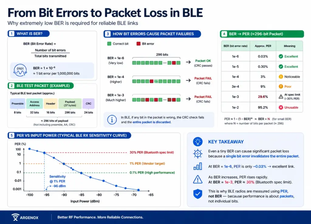
PER is closely related to BER because the bit errors result in packet errors. In many systems at a very low BER (e.g. 1e-6 which means one bit wrong per million), the Packet error rate is tiny and it indicates an excellent excellent link.
However, realistic numbers are a BER of 1e-3, which means roughly 29.6% of packets being lost (assuming 40-50 byte packet) and very close to the Bluetooth specification limit (hence why this number is used).
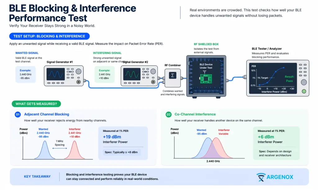
Blocking & Interference Performance
BLE blocking and interference tests verify that a receiver can maintain reliable packet reception in the presence of strong in-band and out-of-band signals, including other BLE devices, Wi-Fi transmissions, and high-power nearby radios.
How well your receiver works in the presence of strong signals nearby is critical in many applications. Although you may not have added multiple radios in your system, your product is surrounded by transmitters constantly like other phones.
These tests are critical especially if you have strong transmitters on the same board, but there’s also other circuitry that can generate interference elsewhere, so it’s critical to test the blocking and interference performance (aside from the fact it’s part of the standard set of Bluetooth SIG PHY Tests)
Why it matters:
- Real environments are noisy (Wi-Fi, LTE, etc.)
- BLE shares spectrum → coexistence is critical
Tests include:
- Adjacent channel rejection
- Co-channel interference
- Wi-Fi coexistence scenarios
Some of these tests are standard BLE PHY tests that need to be passed, but there’s a bigger reason – a harmonic on one of your other transmitters can leak into your radio and cause significant issues. Without good blocking
What do you do when this is an issue? Shielding, filtering and move radios away.
Harmonic Testing
Some of the most critical tests that need to be done for products relate to harmonics. This is because harmonic limits are relatively stringent and they’re more difficult to control.
Harmonics are transmissions in frequencies that are multiples of the base frequency. In this case up to the 5th harmonic needs to be checked which is around 12GHz
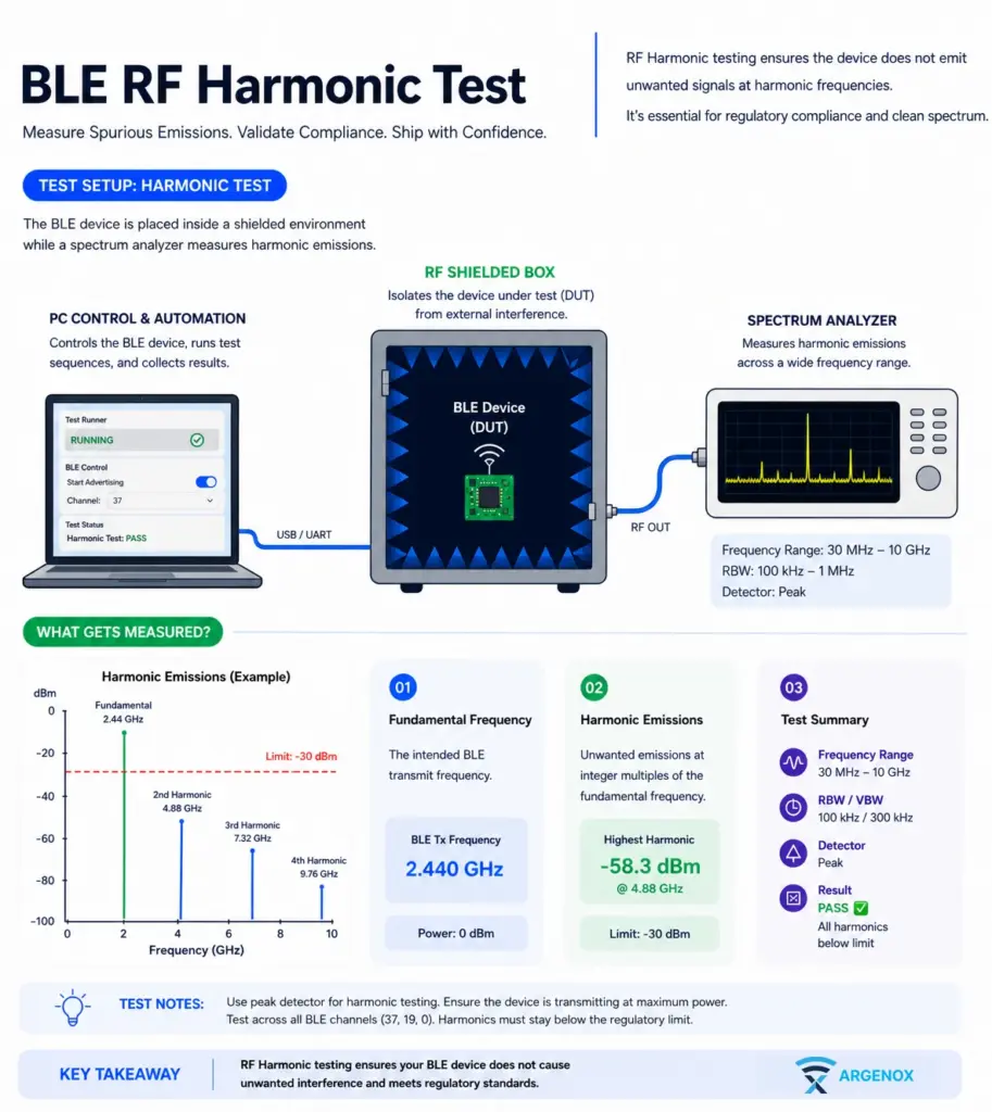
Harmonic measurements are done using a spectrum analyzer in a conducted test setup. The device under test is connected through a coaxial cable, often with attenuation, directly into the measurement equipment. This removes variability from antennas and the environment, allowing you to evaluate the raw RF performance of the transmitter.
One of the more confusing aspects of harmonic testing is that your measurement equipment and the regulatory limits are not expressed in the same units. A spectrum analyzer in a conducted setup measures power in dBm. You connect your device through a cable, and the analyzer reports how much power is present at each frequency. This is a direct electrical measurement at the RF port.
Regulatory limits, however, are often specified in terms of radiated field strength, typically in units like dBµV/m measured at a defined distance, such as 3 meters. This represents how strong the signal appears in free space when radiated from the device.
To compare your measured harmonics against these limits, you need to translate between conducted power and radiated field strength.
For example, FCC radiated emission limits above 960 MHz are commonly expressed as 500 µV/m measured at 3 meters, which is the same as 54 dBµV/m. This corresponds to about −41.23 dBm EIRP.
Conducted vs Radiated Testing
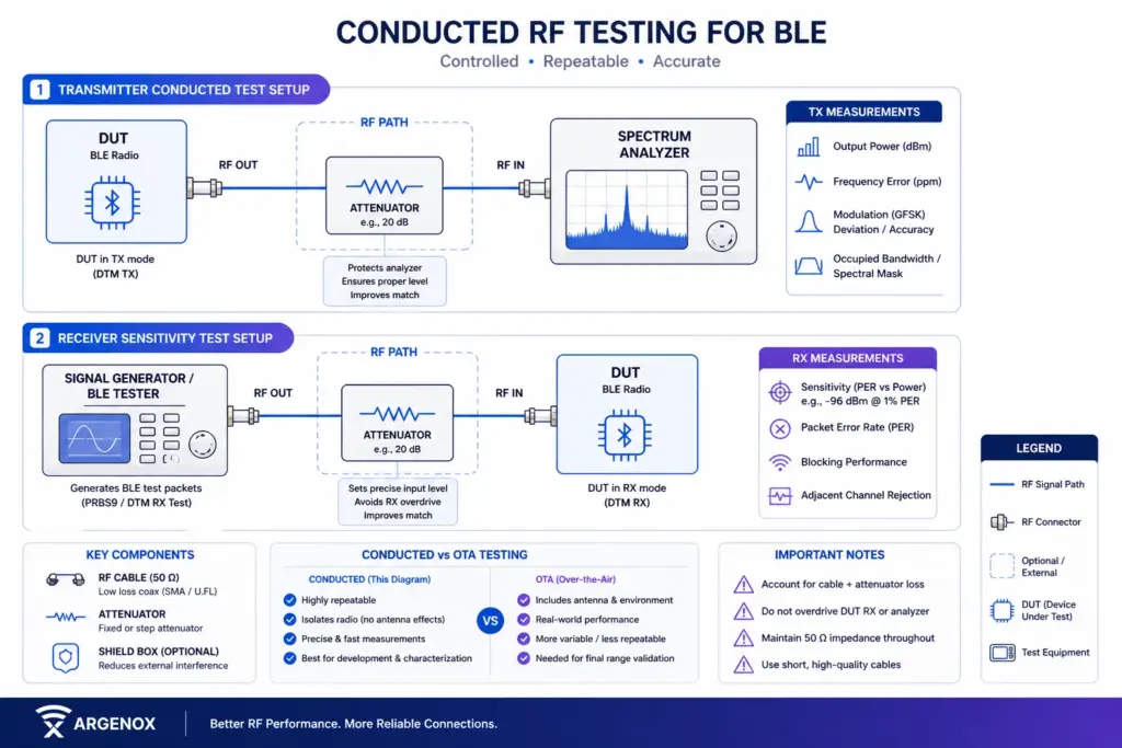
Conducted RF Testing in Bluetooth and BLE
Conducted testing is the most controlled way to measure BLE radio performance. Instead of relying on antennas and over-the-air signals, you connect the radio directly to test equipment using RF cables. This removes environmental variables and lets you measure the radio itself with high precision.
Conducted RF tests let you eliminate reflections, multipath, or environmental noise from the setup so you get the same results every time. It also eliminates interference from other transmitters in your environment
Usually these tests are done in an RF shielded box to help prevent signals from leaking in in other ways. The box typically has a filtered RF port and a USB connector that let’s you bring in power and data to isolate the board.
Good RF shielded boxes provided 90dB and more of isolation
- Direct RF connection via coax
- Removes antenna effects
- Highly repeatable
Used for:
- Bring-up and debugging
- RF characterization
- Sensitivity and PER testing
- Comparing chip performance
Conducted tests are usually easier to do compared to radiated because you can use a relatively low-cost RF shielded box and cables (sometimes you can even avoid the box).
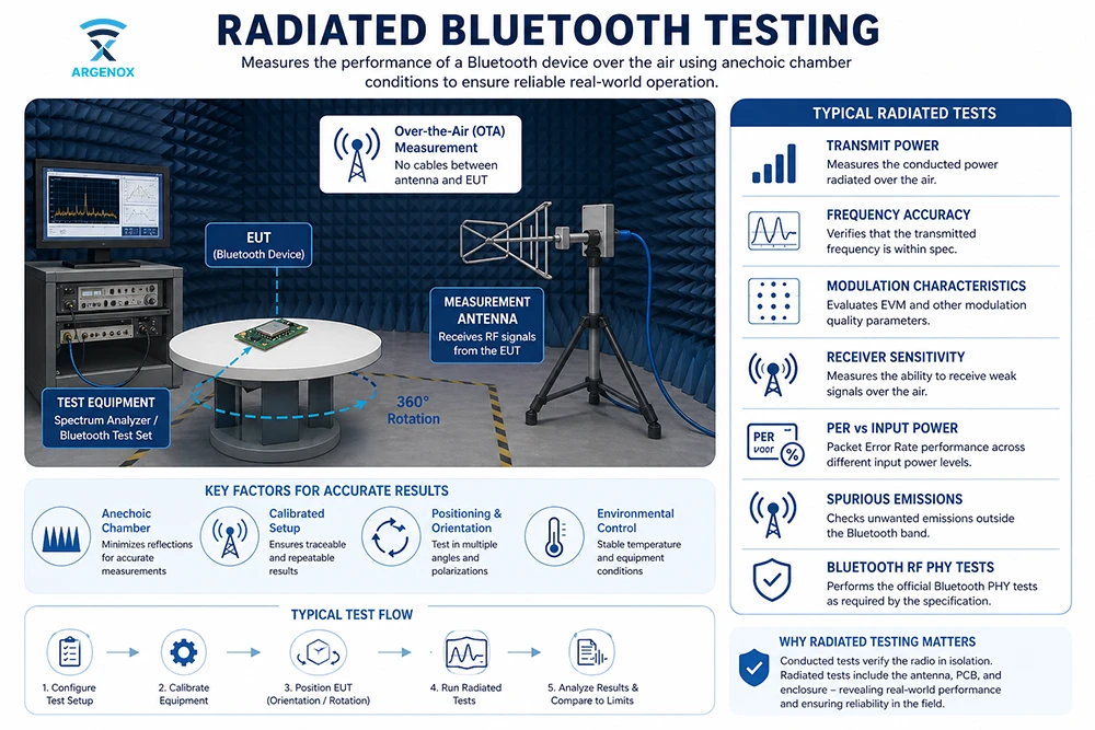
Radiated Bluetooth Testing
The conducted BT testing helps you eliminate one of the most common sources of variability – your antenna. Antennas are complicated because they allow any signal to enter your system – your own signal, or copies of that signal that are slightly phase shifted. Sometimes these signals can combine constructively to increase strength, or destructively to cancel each other out.
Once you are sure of the RF performance of your system is solid without the antenna, it’s time to look at the antenna.
In practice you’d do this alongside – you can almost never wait until all the tests are complete before looking at the antenna performance since you’ll be developing a product.
Radiated Testing is done in an RF chamber. It’s a large version of the RF shielded box, one large enough to fit humans, and even cars (or planes if that’s what you’re working on).
While there are what’s typically called a “Screen Room” which is an RF shielded box, an RF chamber, typically called an anechoic chamber, has a second purpose which is to eliminate echoes. It does this using Radiation Absorbent Materials (RAM for short) that attenuates signals transmitted.
This lets you measure the Device (DUT) correctly. The chamber is also shielded, preventing other signals from entering.
In this way
- Tests full system (antenna + enclosure)
- Includes real-world effects
Although some large companies have their own anechoic chambers, most product developers will need to rely on companies to perform this. In addition to having the facilities, you need people with experience operating inside who also understand how to test the device.
The shielded chamber is used to primarily perform antenna testing, but tests such as PER and BER tests are important to validate.
Required Equipment for Bluetooth Testing
Typical RF PHY testing setup includes:
- BLE Tester (e.g., Rohde & Schwarz, Keysight Technologies, Anritsu, Litepoint, etc)
- Spectrum analyzer
- Signal generator
- RF shield box
- Programmable attenuator
- Temperature chamber (for drift testing)
You’ll need multiple devices being tested, ideally as close to the final product as possible.
Bluetooth SIG RF PHY Tests
The Bluetooth SIG defines formal RF PHY tests for qualification and is split into two major sets of tests:
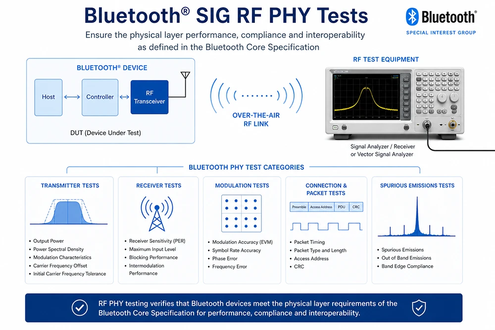
- Transmitter tests:
- Output power
- Frequency accuracy
- Modulation characteristics
- Receiver tests:
- Sensitivity
- Blocking
- Intermodulation
To release a product you have to pass these tests at a certified lab which provides a report. This report is uploaded during the Qualification process.
Even though there’s a large set of mandatory RF and protocol tests defined by the Bluetooth SIG, the exact test scope depends on the Implementation Conformance Statement (ICS), where a device declares the features it supports. Only the tests that apply to the declared features are required. For example, if a device doesn’t support the LE 2M PHY, then the associated RF PHY tests for that feature are not required.
Taking the time to define the features you’ll need early in the design phase can make the qualification process significantly easier.
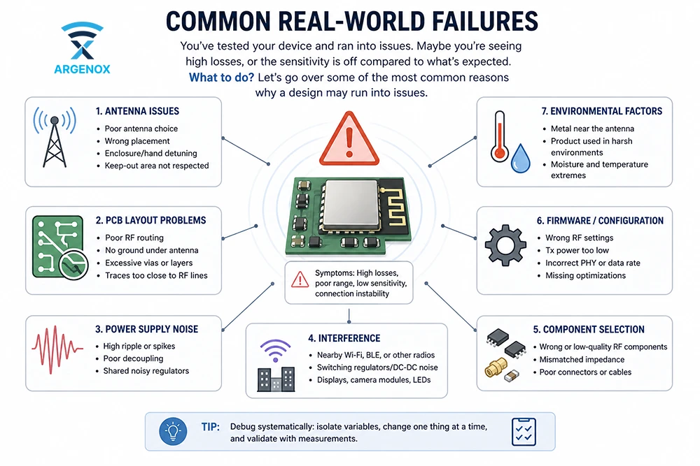
Common Real-World Failures
So you’ve tested your device and ran into issues. Maye you’re seeing some high losses, or the sensitivity is off compared to what’s expected. What to do? Let’s go over some of the most common reasons why a design may run into issues.
Power Supply Noise → Bad Modulation
Your RF chip generates radio frequency signals and depends on a clean power supply. Batteries are a clean power source, but many designs integrate a DC/DC power supply. In fact, most BLE chips today include a DC/DC converter themselves.
One secret is that in many cases enabling this DC/DC supply, which reduces the current consumption significantly, will cause the sensitivity to drop. It’s not uncommon to see around 2dB of sensitivity loss (called desense) in system.
But other complicated systems can have many other power supplies and switching regulators that could cause sensitivity and other issues.
The fix here depends on the issue – in some cases, better layout and isolation can help, while in others the frequency of the power supply may need to be adjusted to avoid harmonics that affect the radio.
Some of this is trial and error – try to eliminate the regulator with an LDO for testing and see whether the performance improves. If it does then it needs to be done.
Poor RF Impedances
RF design is commonly called a Black Art because of the challenge in designing it. But a good RF designer knows what to do to get a proper impedance.
All RF systems use a standard 50 ohm impedance, and keeping this impedance consistent in the RF section of the circuit is critical to ensure all power is delivered. This means proper stackup and trace design which has to be designed from the start.
Poor Antenna Matching
If impedance design is critical, in the antenna it’s even more so. Making sure that all the RF power reaches the antenna impacts output power and sensitivity. Antenna matching depends on may factors, and an antenna can be detuned by metal and dielectric.
How a person holds the device or wears it can have a significant impact on the antenna tuning. Everything needs to be taken into account, so the antenna performs at its best.
Antenna tuning is done either using lumped components (capacitors and inductors) or distributed elements (traces). The antenna matching network is one place where many designers make mistakes, including in the component selection.
Crystal Issues
Frequency drive and connection issues are usually directly traced to the crystal. If it’s not properly tuned, or the crystal is poor.
Temperature affects crystal and they can drift, requiring
- Cheap or poorly loaded crystal → frequency drift
- Fix: proper load caps, TCXO if needed
PCB Layout Problems
RF layout and general PCB layout can turn traces on the board into efficient antennas (traces tend to be bad radiators, but they do radiate). These antennas can couple energy where you don’t want it.
Typically, Radios need to be isolated, and in many cases additional shielding like RF cans can help improve. But don’t fix bad layout issues by just shielding – attack the source:
- Ground discontinuities where there’s no continuous ground plane allowing signals to have a tightly coupled return path
- RF trace impedance mismatch
Other issues can include signals with fast edges like clocks (which means significant harmonics). Keeping these away from the radio will help prevent issues.
Practical Testing Strategy
Over 12 years of RF testing of Bluetooth radios has given us some insight into flows that help avoid a lot of the issues one sees in designs. We like to be proactive and test early and often to make sure that the radio performs as expected, and to leverage known good designs whenever possible.
Here are some of the stages we use. Sometimes we have to change it depending on the device or the timelines.
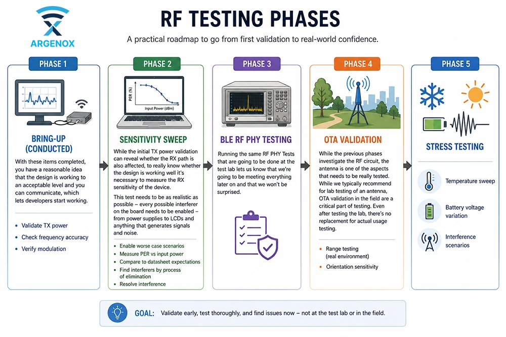
Phase 1: Bring-Up (Conducted)
- Validate TX power
- Check frequency accuracy
- Verify modulation
- Harmonic Testing
With these items completed, you have a reasonable idea that the design works to an acceptable level and you can communicate, which lets developers start working.
We will also perform some basic harmonic testing to make sure nothing is exceeding the limits.
Phase 2: Sensitivity Sweep
While the initial TX power validation can reveal whether the RX path is also affected, to know whether the design is working well it’s necessary to measure the RX sensitivity of the device.
This test needs to be as realistic as possible – every possible interferer on the board needs to be enabled – from power supplies to LCDs and anything that generates signals and noise.
- Enable worse case scenarios
- Measure PER vs input power
- Compare to datasheet expectations
- Find interferers by process of elimination
- Resolve interference
Phase 3: BLE RF PHY Testing
Running the same RF PHY Tests that are going to be done at the test lab let’s us know that we’re going to be meeting everything later on and that we won’t be surprised.
Phase 4: OTA Validation
While the previous phases investigate the RF circuit, the antenna is one of the aspects that needs to be really tested. While we typically recommend lab testing of an antenna, OTA validation in the field are a critical part of testing. Even after testing the lab, there’s no replacement for actual usage testing
- Range testing (real environment)
- Orientation sensitivity
Phase 5: Stress Testing
Even with OTA validation, most real-world scenarios won’t push the system to its limits. For that and to get real data it’s necessary to run tests for environmental factors:
- Temperature sweep
- Battery voltage variation
- Interference scenarios
Final Thoughts
RF PHY testing is where theoretical design meets physical reality. It’s not just about passing certification. It’s about making sure your BLE product behaves reliably in noisy, unpredictable environments where you get the most out of the radio.
If you’re building serious BLE products (medical, industrial, or high-volume consumer), investing in proper RF validation workflows will save months of debugging and protect your product reputation. As an alternative, using modules can save significant RF effort, though it won’t eliminate the antenna aspect which is as critical as the rest of the RF.